Stretch Forming Formulas: Bending Radius, Force & Springback
Master the technical physics of stretch forming. Explore essential engineering formulas for minimum bending radius, tensile force, springback compensation, and Poisson effect shrinkage.
Precision in industrial profile bending is governed by the laws of material mechanics. This technical guide provides the core formulas required to predict material behavior, ensuring geometric accuracy across aerospace, automotive, and architectural applications.
For the stretch forming of industrial profiles (especially aluminum curtain wall extrusions), the forming capability and mechanical requirements are calculated using the following core formulas:
1. Rmin≈H/(2*δ)
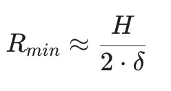
Minimum Bending Radius (Rmin)
Minimum Bending Radius (Rmin): The minimum bending radius is the physical limit beyond which the material’s surface may crack or fail. It is primarily determined by the section height and the material’s elongation properties.
To prevent material fracturing on the outer surface or excessive section distortion, the minimum radius is determined by the material’s elongation property:
Rmin≈H/(2*δ)
- H: The height of the profile cross-section in the bending direction.
- δ: The elongation of the material (uniform elongation).
Note: While the theoretical formula provides a baseline, for high-precision industrial applications, we recommend applying a safety factor of 1.5x to the Rmin to ensure surface finish integrity. In practice, to ensure safety and surface quality, the radius is typically set at R > (1.5 -2) *Rmin.
2. F = A*σₛ*k
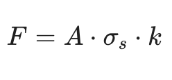
Required Tensile Force (F)
The tensile force is the amount of pull required to bring the entire cross-section of the profile into a plastic state. Accurate calculation ensures that the chosen machine has sufficient tonnage and that the material is not over-stressed.
To bring the profile into a plastic state and eliminate springback, the machine must apply a force that exceeds the material’s yield point:
F = A*σₛ*k‘
Where:
- •F — Required tensile force (N)
- •A — Cross-sectional area of the profile (mm²)
- •σₛ — Yield strength of the material (MPa)
- •k — Stretch coefficient (typically 1.05 – 1.25)
- •k≈1.05: Initial plastic deformation.
- •k≈1.2: Post-stretching to maximize springback reduction.
Engineering Note:
To convert the result from Newtons ($N$) to the Machine Tonnage (Tons), use the following conversion:
Tons = F (N)/9810
It is recommended to select a machine with a rated capacity 20-30% higher than the calculated required force to ensure long-term hydraulic stability and handle material batch variations.
3. ∆ R = R*(σₛ/E)
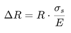
Springback Estimation (∆R)
Springback is the elastic recovery that occurs when the stretching tension is released. In the stretch forming process, while axial tension significantly reduces springback compared to roll bending, it is never entirely eliminated. Predicting this change is essential for designing the correct die radius.
Springback is the most critical variable in curtain wall fabrication. A simplified engineering estimation is:
∆ R = R*(σₛ/E)
- R: The radius of the forming die.
- E: The Modulus of Elasticity (approx. 70,000 MPa for aluminum alloys).
- Insight: A higher yield strength (σₛ) results in greater springback, while a higher Modulus of Elasticity (E) reduces it.
- Final Part Radius Rfinal:The actual radius of the finished component is the sum of the die radius and the springback: Rfinal= R + ∆ R
- Why Stretch Forming is Superior:In conventional bending, springback can be as high as 5%–10%. However, in the Stretch Forming Process, by applying high axial tension (k > 1.1), we “lock” the fibers into a plastic state, often reducing the springback to less than 0.5%–1%.
- The Role of CNC Control:Modern CNC systems, like those in our PBF series, use these formulas as a baseline but also perform real-time compensation based on material batch variations (actual yield strength vs. nominal yield strength).
4. ∆ W = W0 * ε* ν
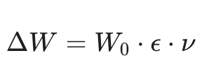
Sectional Width Shrinkage (The Poisson Effect)
During the stretch forming process, as the profile is stretched longitudinally to control springback, a simultaneous contraction occurs in the cross-section. This phenomenon, known as the Poisson Effect, results in a slight reduction in the profile’s width and height.
Calculate the physical contraction of the profile width.
∆ W = W0 * ε* ν
Where W 0 is original width, ε is elongation, and $ν is the Poisson’s ratio 0.33.
Engineering Impact for Production
To help your customers understand why this calculation matters, you can add these professional insights:
- Final Width Wfinal:The final dimension of the profile after forming is: Wfinal = W0 – ∆ W
- Critical Tolerances:For high-precision applications, a 2% elongation on a 100 mm wide profile will result in a 0.66 mm reduction in width. This can be critical for:
- Glass Groove Clearance: Ensuring the glass and gaskets still fit correctly.
- Snap-on Covers: Maintaining the integrity of clip-on components.
- Thermal Break Strips: Ensuring the structural bond remains tight.
- Compensation Advice:If your project has extremely tight tolerances, this shrinkage should be factored into the initial extrusion die design or compensated for during the tooling setup.